

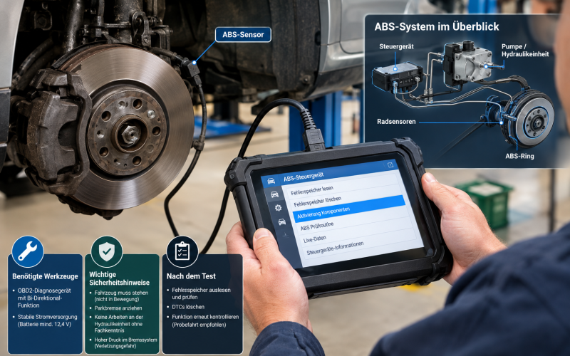
ABS Test Activation | How to Run an ABS Actuator Test Safely
An ABS test activation is a diagnostic procedure in which a scan tool commands components of the anti-lock braking system—such as the hydraulic pump motor and individual solenoid valves—to operate while the vehicle is stationary. It is commonly called an ABS actuator test, ABS functional test, or ABS service test.
The procedure can help determine whether an ABS control unit can communicate with the hydraulic unit and whether commanded components respond. Depending on the vehicle, the diagnostic system may allow you to activate the ABS pump, inlet and outlet valves, traction-control valves, or other hydraulic functions. HELLA describes the actuator test as a diagnostic function in which individual components can be actively commanded and their operation checked.
The important limitation is that there is no universal ABS test sequence for every vehicle. Activation conditions, available tests, command duration, battery-voltage requirements, parking-brake position, and whether the brake pedal must be pressed vary by manufacturer and ABS generation. A vehicle-specific workshop manual and the instructions displayed by the diagnostic tool take priority over any generic procedure.
Safety warning: ABS, ESC/ESP and the associated hydraulic brake system are safety-critical systems. An incorrect actuator test, incorrect hydraulic work, or an improperly completed repair can affect braking performance or electronic stability functions. Do not open brake lines, loosen hydraulic fittings, or attempt to dismantle an ABS hydraulic unit merely to perform an actuator test. If the procedure requires hydraulic-system intervention, follow the manufacturer’s repair instructions.
What Is an ABS Test Activation?
During normal driving, the ABS control unit monitors wheel-speed sensors and other inputs and controls hydraulic valves and the pump when wheel lock is detected.
An actuator test reverses the normal relationship: instead of waiting for the ABS system to decide that an intervention is necessary, the diagnostic equipment sends a specific command to the ABS control unit.
A typical test may command:
- ABS hydraulic pump motor
- Individual inlet or outlet solenoid valves
- Traction-control or stability-control valves
- Hydraulic pressure-building or pressure-reduction functions
- Bleeding or hydraulic-unit routines on supported vehicles
The exact list depends on the ABS/ESC system fitted to the vehicle. Some diagnostic platforms show individual wheel valves, while others provide a guided ABS or hydraulic-unit routine instead. Diagnostic equipment manuals also commonly distinguish between an active test and other service functions, with the available actuators determined by the vehicle and system being diagnosed.
ABS test activation vs. reading ABS fault codes
These are different diagnostic operations.
| Function | What it does | Typical purpose |
|---|---|---|
| Read DTCs | Retrieves stored diagnostic trouble codes | Identify recorded faults |
| Live data | Displays current sensor and system values | Check wheel speeds, voltage and other parameters |
| Actuator test | Commands an output to operate | Check pump/valve response |
| Basic setting/calibration | Performs a defined calibration or initialization | Restore required learned/reference values |
| Hydraulic bleeding routine | Operates valves/pump according to a defined procedure | Remove air after applicable brake-system work |
HELLA recommends beginning ABS diagnosis by reading the fault memory and then evaluating parameters where appropriate. An actuator test is a further diagnostic option rather than a substitute for reading and interpreting the stored faults.
What You Need Before Performing an ABS Actuator Test
The correct equipment matters because a basic code reader is not necessarily capable of commanding an ABS actuator.
1. A diagnostic scanner with ABS access
Use a diagnostic device that supports:
- ABS/ESC control-unit communication
- Manufacturer-specific diagnostics where required
- Live data
- DTC reading and clearing
- Bidirectional control or active tests
- ABS actuator testing for the particular vehicle
- Guided functions where applicable
The fact that a tool has an OBD2 connector does not automatically mean it can access every ABS function. HELLA notes that the diagnostic process requires correct vehicle/system identification and that additional diagnostic interfaces or adapters may be required for some applications.
2. Stable vehicle power
The ABS control unit and hydraulic pump can be sensitive to inadequate electrical supply.
Check the battery and charging system before beginning. The required voltage is vehicle-specific. For example, one Mitsubishi ABS service procedure specifies 10 V or more as a normal battery-voltage condition for a monitored ABS parameter, while other systems have different thresholds and test requirements.
Do not turn a value from another vehicle into a universal rule such as “ABS always needs 12.6 V.” Instead, use the manufacturer’s specified minimum voltage and connect a suitable battery support unit when the workshop procedure calls for one.
HELLA also emphasizes that sufficient battery voltage is required for reliable communication with the control unit.
3. Vehicle-specific service information
Before selecting ABS Test, Actuator Test, Active Test, or a similar function, confirm:
- Vehicle make, model and model year
- ABS/ESC system variant
- Required ignition state
- Transmission position
- Parking-brake condition
- Brake-pedal condition
- Vehicle-speed requirement
- Battery-voltage requirement
- Whether wheels must remain on the ground
- Whether the vehicle must be lifted
- Whether the engine must be running
- Whether additional safety equipment is required
These conditions are not interchangeable between vehicles.
4. Basic workshop safety equipment
At minimum, use appropriate:
- Wheel chocks where specified
- Personal protective equipment
- Brake-fluid-resistant gloves where hydraulic work is involved
- Suitable lighting
- Approved battery support equipment where required
- Manufacturer-approved lifting equipment if the procedure calls for a raised vehicle
Never rely on the parking brake alone to secure a vehicle during workshop work.
Conditions Required Before ABS Test Activation
The most important point is that an ABS actuator test is normally a controlled workshop procedure, not a driving test.
Vehicle speed: normally stationary
Many ABS systems permit actuator activation only while the vehicle is stationary.
For example, Mitsubishi service information states that its ABS actuator test can only be performed with the vehicle stationary and that forced actuator operation is disabled if vehicle speed reaches approximately 10 km/h. Another Mitsubishi procedure similarly specifies stationary operation.
This does not mean 0 km/h is a universal software threshold for every vehicle. Some systems may use their own conditions or cancel the test if a movement signal is detected.
For a generic procedure, the safe rule is:
Keep the vehicle stationary and follow the scan tool’s displayed conditions exactly.
Parking brake status
The parking-brake requirement is also vehicle-dependent.
Do not assume that the parking brake should always be applied or always released. Some tests may require a particular parking-brake state, transmission position, or wheel-securing procedure.
If the diagnostic tool reports:
- “Parking brake not in required position”
- “Conditions not met”
- “Vehicle not stationary“
- “Brake pedal condition incorrect”
correct that condition before attempting the test again.
Brake pedal position
Some hydraulic tests require the brake pedal to be depressed; others require the pedal to be released.
This matters because the actuator may intentionally increase, hold or reduce hydraulic pressure. A service manual may specify an assistant at the brake pedal or a particular pedal position.
Never improvise this condition when the manufacturer’s procedure specifies otherwise.
Ignition and engine state
The test may require:
- Ignition ON, engine OFF
- Ignition ON, engine running
- A specific diagnostic mode
- A completed ABS self-check
- No active disabling fault
Older Mitsubishi documentation, for example, states that actuator testing cannot be performed when the ABS ECU has been disabled and that the ABS warning lamp can illuminate while the actuator test is running.
How to Perform an ABS Test Activation With a Diagnostic Scanner
The following is a general diagnostic workflow, not a substitute for the manufacturer’s test sequence.
Step 1: Secure the vehicle
Park the vehicle on a suitable level surface unless the manufacturer’s procedure specifies otherwise.
Select the required transmission position and secure the vehicle according to the workshop instructions. Use wheel chocks when appropriate.
Make sure nobody is standing near rotating wheels or moving mechanical components.
If the test requires the vehicle to be raised, use an approved lift and follow the manufacturer’s lifting points. Do not improvise a wheel-off-ground test.
Step 2: Check the basic brake system
Before commanding the ABS hydraulic unit, inspect the obvious basics:
- Brake-fluid level
- Visible hydraulic leaks
- Brake-pipe condition
- ABS wiring and connectors
- Relevant fuses
- Battery condition
- Wheel-speed sensor wiring
- ABS warning lamps
A fault in a wheel-speed sensor or its wiring can produce an ABS DTC without the ABS hydraulic unit itself being defective.
HELLA specifically recommends visual inspection of wheel and sensor components and checking the brake system before progressing through electronic ABS diagnosis.
Step 3: Connect the diagnostic scanner
With the ignition switched off if required by the tool, connect the diagnostic interface to the vehicle’s diagnostic connector.
Then:
- Switch the ignition to the state specified by the diagnostic system.
- Identify the vehicle accurately.
- Select the correct ABS/ESC system.
- Establish communication.
- Confirm that the scanner identifies the expected control unit.
If the tool cannot communicate with the ABS module, do not proceed by repeatedly sending actuator commands.
First check:
- Battery voltage
- Diagnostic connector power and ground
- Relevant ABS fuses
- CAN or other communication wiring
- Correct vehicle/system selection
- Manufacturer security or gateway requirements
A communication failure is a different diagnostic problem from a failed ABS pump.
Step 4: Read and record the DTCs first
Before clearing anything, save or record:
- DTC number
- DTC description
- Status
- Freeze-frame information where available
- Relevant live-data values
- Warning lamps currently illuminated
Do not immediately erase the fault memory just because an actuator test is about to be performed.
A DTC identifies a monitored fault condition; it does not automatically prove that the named component itself must be replaced. HELLA explicitly cautions that a stored fault code may provide an indication of the cause without necessarily proving that the component is defective.
Step 5: Open the actuator or active-test menu
Depending on the diagnostic platform, the function may be called:
- Actuator Test
- Active Test
- Output Test
- Component Activation
- ABS Test
- Hydraulic Unit Test
- Pump Motor Test
- Solenoid Valve Test
- Functional Test
Select the ABS/ESC actuator function appropriate to the vehicle.
Do not select an apparently similar function simply because its name contains “ABS.” Some menus contain bleeding, calibration, service-mode and actuator functions that have completely different purposes.
Step 6: Confirm the test conditions
The scanner may display a list of prerequisites.
Typical examples include:
- Vehicle stationary
- Ignition ON
- Engine OFF or running, depending on the system
- Transmission in the specified position
- Parking brake in the specified state
- Brake pedal released or depressed as instructed
- Adequate battery voltage
- No incompatible diagnostic routine currently active
Complete the conditions shown on screen before selecting Start, Activate, or OK.
Step 7: Activate the ABS pump or selected actuator
If the vehicle supports direct pump activation, select the pump motor.
The scanner may display a timed command such as a short activation period. Do not extend the command manually unless the manufacturer explicitly permits it.
When the pump is commanded, you may hear an electric motor or hydraulic-unit buzzing sound.
Depending on the hydraulic design and test routine, you may also feel:
- Brake-pedal movement
- Pedal pulsation
- Changes in pedal resistance
- Hydraulic-unit clicking
- Solenoid-valve operation
These sensations can be normal during a correctly executed actuator test. They are not, by themselves, proof that the entire ABS system is functional.
A pump that makes noise demonstrates that the motor is responding acoustically, but it does not automatically prove correct hydraulic pressure generation, valve operation, wheel-speed sensing or ABS intervention during driving.
Step 8: Test individual valves where supported
Some systems allow the technician to activate individual inlet and outlet valves.
The scan tool may present entries such as:
- Front-left inlet valve
- Front-right inlet valve
- Rear-left inlet valve
- Rear-right inlet valve
- Front-left outlet valve
- Front-right outlet valve
- Rear-left outlet valve
- Rear-right outlet valve
The exact configuration varies considerably.
Some systems instead use a guided routine that automatically controls several valves and the pump in a defined sequence.
Follow the tool’s instructions rather than trying to recreate a factory routine manually.
Step 9: Observe the result
During the test, compare three things:
Command: Did the diagnostic tool confirm that the command was sent?
Electrical response: Did the control unit report the actuator as operating or change an associated parameter?
Physical response: Did the expected motor, valve or hydraulic action occur?
A “test completed” message is not necessarily equivalent to a complete mechanical diagnosis.
For example:
The scan tool commands the pump → the pump produces the expected sound → but a manufacturer-specified pressure or hydraulic response is absent.
That combination points toward a deeper hydraulic or pump-system investigation rather than simply declaring the ABS system healthy.
Step 10: Stop the test normally
Use the scanner’s Stop, End, or Back function when instructed.
Do not disconnect the diagnostic connector while an actuator is being commanded unless the service procedure specifically requires it.
Allow the control unit to return to its normal state.
What Should You Hear or Feel During an ABS Test?
There is no single sound or pedal sensation that applies to every ABS system.
A functioning pump motor may produce a noticeable electric-motor buzzing or whirring sound. Solenoid valves can produce distinct clicks. Hydraulic routines can produce changes in brake-pedal resistance or pulsation.
The significance of the response depends on the test being performed.
| Observation | Possible interpretation |
|---|---|
| Pump runs and produces expected sound | Electrical command and motor operation may be present |
| No pump sound | Possible power, fuse, relay, wiring, control-unit or motor problem |
| Valve clicks but hydraulic response is absent | Possible hydraulic, valve or pressure-related fault |
| Pedal pulsates during an appropriate hydraulic routine | Can be a normal response |
| Scanner reports command unavailable | Test conditions may not be satisfied |
| Test stops immediately | Vehicle condition, fault status or communication may have interrupted the routine |
| New DTC appears during test | The test may have detected an electrical, hydraulic or communication problem |
These observations are diagnostic clues—not standalone diagnoses.
Why the ABS Pump May Not Activate
If the scan tool refuses to activate the ABS pump, work through the problem systematically.
1. The test conditions are not satisfied
This is one of the simplest explanations.
Check the displayed requirements for:
- Vehicle speed
- Ignition state
- Engine state
- Transmission position
- Parking brake
- Brake pedal
- Battery voltage
- Active diagnostic mode
Some systems deliberately inhibit actuator operation when an ABS ECU fault is present. Mitsubishi service documentation provides an example where actuator testing is unavailable when the ABS ECU has been disabled.
2. Battery voltage is too low
A weak battery or unstable supply can cause:
- Failed communication
- Test cancellation
- Control-unit reset
- Actuator underperformance
- Additional voltage-related DTCs
Do not use a generic voltage threshold as a substitute for the vehicle manufacturer’s specification.
3. The scanner does not support the function
A scanner can communicate with an ABS module yet still lack bidirectional control.
If you can read ABS DTCs but cannot find an actuator-test menu, check whether the tool supports active testing for that exact vehicle and ABS system.
4. The ABS module has an active fault
Some control units restrict certain actuator functions when a serious internal, electrical or communication fault is present.
Read the DTCs before assuming the pump itself has failed.
5. Power, ground, fuse or wiring fault
An ABS hydraulic unit contains electrically controlled components and a pump motor. A blown high-current fuse, poor ground, damaged wiring or connector problem can prevent activation.
Check the relevant circuit using the manufacturer’s wiring diagram and test specifications.
6. The pump motor or hydraulic unit may be defective
Only after the power supply, communication, test conditions and relevant wiring have been checked should the hydraulic unit itself become a primary suspect.
Do not replace the ABS control unit simply because the pump did not run during one attempted actuator test.
What to Do When an ABS Actuator Test Fails
A failed actuator test should be treated as a diagnostic result, not a component replacement instruction.
Use this sequence:
- Record the exact test failure message.
- Read the ABS/ESC DTCs again.
- Check whether a new DTC appeared during the test.
- Confirm battery voltage.
- Confirm that the correct actuator and vehicle system were selected.
- Check fuses, power supply and grounds.
- Inspect connectors and wiring.
- Review live data where applicable.
- Follow the manufacturer’s diagnostic test plan.
- Only then determine whether further component-level testing is justified.
A code relating to a pump does not automatically prove that the pump motor is defective. Conversely, a pump that can be heard operating does not prove that the hydraulic unit can generate and control pressure correctly.
High-Pressure Hydraulic Safety
The electrical part of an ABS actuator test is relatively straightforward; the hydraulic system is where additional caution is required.
Some ABS and brake-control systems store or generate hydraulic pressure. Toyota documentation for certain ABS/brake-control systems describes brake fluid stored under high pressure being used for brake assist and ABS hydraulic control.
Manufacturer service documentation also warns that hydraulic fluid can be released with considerable force when working on high-pressure ABS-related systems.
Never assume an actuator test has depressurized the system
Do not loosen:
- Brake pipes
- Hydraulic fittings
- Bleeder components
- Accumulator connections
- ABS-unit connections
unless the manufacturer specifically provides a depressurization procedure and you are following it.
If hydraulic components have been opened or replaced, the correct refill and bleeding procedure must be completed. Nissan service documentation, for example, specifies refilling and bleeding after ABS actuator installation.
Brake fluid is also a contamination issue
Keep dirt, oil and other fluids away from the brake hydraulic system.
Use only the brake fluid specification required by the vehicle manufacturer. Never introduce an incompatible fluid into the reservoir.
If brake fluid reaches painted surfaces, clean it according to the applicable service procedure because brake fluid can damage automotive finishes.
Clearing ABS Diagnostic Trouble Codes After the Test
Do not clear the fault memory before recording the original diagnostic information.
After the actuator test:
- Save the original DTCs and relevant data.
- Complete the necessary repair or diagnostic work.
- Run the required actuator or verification test again.
- Read the DTC memory.
- Confirm whether the original fault remains.
- Clear DTCs only when appropriate.
- Switch the ignition off and restart the vehicle as instructed.
- Recheck the ABS/ESC warning lamps.
- Perform any required calibration or basic setting.
- Carry out the manufacturer’s specified road test.
- Re-scan the vehicle after the test drive.
HELLA’s ABS diagnostic procedure similarly includes clearing stored faults after relevant repair work and recommends a final diagnostic check because ABS-related faults can also be stored in other networked control units.
Clearing a DTC does not repair the fault
This distinction is especially important with ABS systems.
If a warning lamp disappears after clearing the memory but the underlying problem remains, the fault can return as soon as the control unit performs the relevant monitoring test.
A successful code erase therefore means only that the stored diagnostic information was cleared. It does not establish that the braking system is repaired.
ABS Test Activation After Brake or ABS Repairs
An actuator test may be only one part of a larger repair procedure.
If you have replaced or disconnected:
- ABS hydraulic unit
- Brake lines
- Brake components
- Wheel-speed sensors
- Steering-angle sensor
- ABS/ESC control unit
- Hydraulic-control components
the vehicle may require additional procedures such as:
- Brake bleeding
- ABS hydraulic-unit bleeding
- Steering-angle calibration
- Yaw/deceleration sensor calibration
- Variant coding
- Control-unit configuration
- Wheel-speed verification
- Road-test validation
The exact requirements depend on the vehicle.
Do not assume that successfully activating the pump means that a newly installed ABS unit is fully commissioned.
ABS Actuator Test vs. ABS Road Test
These procedures answer different questions.
An actuator test asks whether the control unit can command a particular component and whether the expected response occurs under controlled conditions.
A road test evaluates the system under actual vehicle movement and allows parameters such as wheel-speed signals to be assessed dynamically.
For example, HELLA recommends evaluating wheel-speed signals with diagnostic data during a road test when investigating sensor-related problems.
An actuator test cannot prove all of the following by itself:
- Every wheel-speed sensor produces a correct signal
- The ABS activates correctly during emergency braking
- ESC intervention works correctly
- The hydraulic system maintains the required pressure
- The vehicle remains stable under all operating conditions
The final verification must follow the manufacturer’s procedure.
Common Mistakes During an ABS Test
Using a generic OBD2 code reader
A basic OBD2 reader may be sufficient for engine-related emissions diagnostics but may not provide ABS actuator control.
Better approach: confirm ABS/ESC coverage and bidirectional active-test capability before starting.
Treating a DTC as a failed component
A fault code is evidence from the control system, not necessarily a verdict that the named component must be replaced.
Better approach: combine the DTC with live data, electrical checks, visual inspection and the manufacturer’s test plan.
Running the test while the vehicle can move
Many ABS actuator tests are designed for stationary operation and may be automatically cancelled when movement is detected.
Better approach: secure the vehicle and follow the specified stationary conditions.
Using an arbitrary battery-voltage threshold
A value that works for one vehicle may be inappropriate for another.
Better approach: use the manufacturer’s voltage requirement and suitable battery support equipment.
Disconnecting the scanner during activation
Interrupting communication during an active routine can create additional faults or leave the system in an unexpected diagnostic state.
Better approach: stop the routine through the diagnostic software first.
Opening the hydraulic system unnecessarily
An actuator test normally does not require loosening brake lines.
Better approach: keep the hydraulic circuit closed unless the repair procedure specifically requires opening it.
Clearing codes too early
Erasing the fault memory before recording it removes useful diagnostic information.
Better approach: document first, repair second, clear and verify last.
A Practical ABS Test Activation Checklist
Before pressing Activate, confirm:
- Correct vehicle identification
- Correct ABS/ESC system selected
- Diagnostic scanner supports bidirectional control
- Original DTCs recorded
- Battery voltage meets manufacturer specification
- Vehicle is stationary
- Vehicle is securely positioned
- Parking-brake position matches the test instructions
- Transmission position matches the instructions
- Brake pedal position matches the instructions
- No unnecessary hydraulic connections have been opened
- No one is positioned in a hazardous area
- Manufacturer-specific instructions are available
After the test:
- Test completed normally
- Expected pump/valve response observed
- DTCs rechecked
- New faults investigated
- Codes cleared only when appropriate
- Required calibrations completed
- Warning lamps checked
- Required road test completed
- Final diagnostic scan performed
Frequently Asked Questions
What does ABS test activation mean?
ABS test activation is a diagnostic procedure that commands components of the ABS/ESC system to operate so their electrical and, where applicable, hydraulic response can be evaluated. It is usually performed through a diagnostic scanner with active-test or bidirectional-control capability.
Can I activate the ABS pump with an OBD2 scanner?
Only if the scanner supports the vehicle’s ABS/ESC control unit and provides the required active-test function. Having an OBD2 connector does not guarantee access to ABS actuator functions.
Does the vehicle need to be stationary during an ABS actuator test?
Many systems require the vehicle to be stationary. Some manufacturer procedures cancel forced actuator operation if vehicle speed exceeds a specified threshold. Mitsubishi documentation, for example, specifies stationary operation for its actuator tests.
Always follow the conditions displayed by the diagnostic tool and specified by the manufacturer.
Should the parking brake be applied during an ABS test?
There is no universal answer. The required parking-brake state depends on the vehicle and the particular test routine. Use the manufacturer or scanner instructions rather than applying or releasing it based on a generic rule.
What should an ABS pump sound like during activation?
A functioning electric pump may produce a noticeable buzzing or whirring sound. The exact sound varies with the hydraulic unit. A sound alone does not prove correct hydraulic pressure or complete ABS operation.
Why does the brake pedal pulsate during an ABS test?
Pedal movement or pulsation can occur during certain hydraulic actuator routines because the system is deliberately changing hydraulic pressure. It can be a normal part of the specified test, but the expected response must be judged against the vehicle-specific procedure.
Can I clear ABS fault codes after the actuator test?
Yes, when the diagnostic procedure calls for it, but record the original codes first and investigate the cause. Clearing a DTC does not repair an underlying fault.
Can an ABS actuator test damage the braking system?
A correctly performed, manufacturer-supported actuator test is designed as a diagnostic function. The risk comes from using an incorrect procedure, ignoring test conditions, interfering with the hydraulic circuit, or continuing despite abnormal system behavior. Because ABS is safety-critical, follow the vehicle-specific service instructions.
Does a successful ABS pump test prove that the ABS system is working?
No. It demonstrates only what that particular test verifies. Wheel-speed sensors, hydraulic pressure control, valves, communication, calibration and dynamic ABS/ESC operation may require additional tests.
Do I need to bleed the brakes after an ABS actuator test?
Not normally simply because an electrical actuator test was performed. If the hydraulic circuit was opened, an ABS hydraulic unit was replaced, or the manufacturer’s procedure specifies bleeding, the appropriate brake and ABS bleeding procedure must be completed. Manufacturer service documentation can require bleeding after ABS actuator installation.
Conclusion Treat ABS Test Activation as a Diagnostic Procedure, Not a Simple Button Test
An ABS test activation is most useful when it is treated as one stage of a structured diagnosis.
The basic workflow is straightforward: identify the correct ABS system, record existing DTCs, confirm battery voltage and vehicle conditions, use a scanner with the required bidirectional-control capability, run the manufacturer-approved actuator test, observe the commanded response, investigate any failures, and perform the required final verification.
The details are where vehicle-specific information matters. Stationary operation is common, but speed limits, parking-brake position, pedal position, voltage thresholds and available actuator functions vary between systems. Manufacturer documentation should always take priority over a generic checklist.
Most importantly, remember that an ABS pump test is not equivalent to a complete brake-system test. The braking and stability-control systems must be returned to a verified, fault-free operating condition before the vehicle is released for normal road use.